EAS-axial
|
 |
Overload protection for linearly moved masses
-
Reliable force limitation
-
High axial stiffness
-
Automatic engagement
-
Electrical drive disconnection by an integral sensor
|
|
|
|
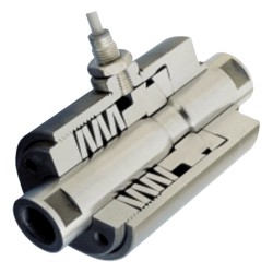
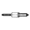
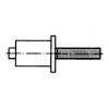
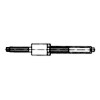
Basic element
|
|
Overload protection for
linearly moved masses.
High axial stiffness. Backlash-free design.
Rapid force drop.
Overload can be signalled by means of a
contactless limit switch.
|
|
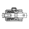
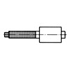
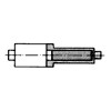
Exterior flange design
|
|
Force transmitted via bolt
and exterior flange.
Free strokes in tensile and / or compressive
directions based on customer supplied
attachment parts. Use for example in feed
carriages.
|
|
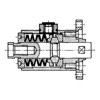
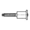
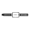
Basic element with sleeve
|
|
Force transmitted via bolt
and threaded end of
sleeve. Free strokes in compressive direction
can be varied by customer supplied attachment
parts up to a maximum limited by the sleeve
length. Sleeve length acc. to customer’s
request in dependence on the reduced length.
|
|
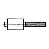
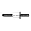
Basic element with connecting rod
|
|
Force transmitted via
connecting rod and bolt
pattern on housing. Connecting rod length is as
required to accommodate the free stroke in a
compressive direction based on customer’s
application.
|
|
Exterior flange design with connecting rod
|
|
Force transmitted via
connecting rod and
exterior flange. Connecting rod length is as
required to accommodate the free stroke in
compressive direction based on customer’s
application.
|
|
Basis element with sleeve and connecting rod
|
|
Force
transmitted via connecting rod and
threaded end of sleeve. Length of the
connecting rod and sleeve are as required to
accommodate free stroke in compressive
direction based on customer’s application.
|
|
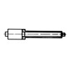
Basic element with guide rod
|
|
Force
transmitted via bolt and housing.
Guide rod length is as required to accommodate
stroke in a tensile direction based on customer’s
application.
|
|
Exterior flange design with guide rod
|
|
Force
transmitted via bolt and exterior flange.
Guide rod length is as required to accommodate
stroke in a tensile direction based on customer’s
application.
|
|
Basic element with guide rod and sleeve
|
|
Force
transmitted via bolt and threaded end of
sleeve.
Length of guide rod and sleeve are as required
to accommodate the free stroke in a tensile
direction based on customer’s application.
|
|
Basic element with connecting rod and guide rod
|
|
Force
transmitted via connecting rod and bolt
pattern on housing.
Length of connecting rod and guide rod are as
required to accommodate free strokes in tensile
and compressive directions based on
customer’s application.
|
|
Exterior flange design with connecting rod and guide rod
|
|
Force
transmitted via connecting rod and
exterior flange.
Length of connecting rod and guide rod are as
required to accommodate free strokes in tensile
and compressive directions based on
customer’s application.
|
|
Basic element with connecting rod, guide rod, and sleeve
|
|
Force
transmitted via connecting rod and
threaded end of sleeve.
Length of connecting rod, guide rod, and
sleeve are as required to accommodate free
strokes in tensile and compressive directions
based on customer’s application.
|
|